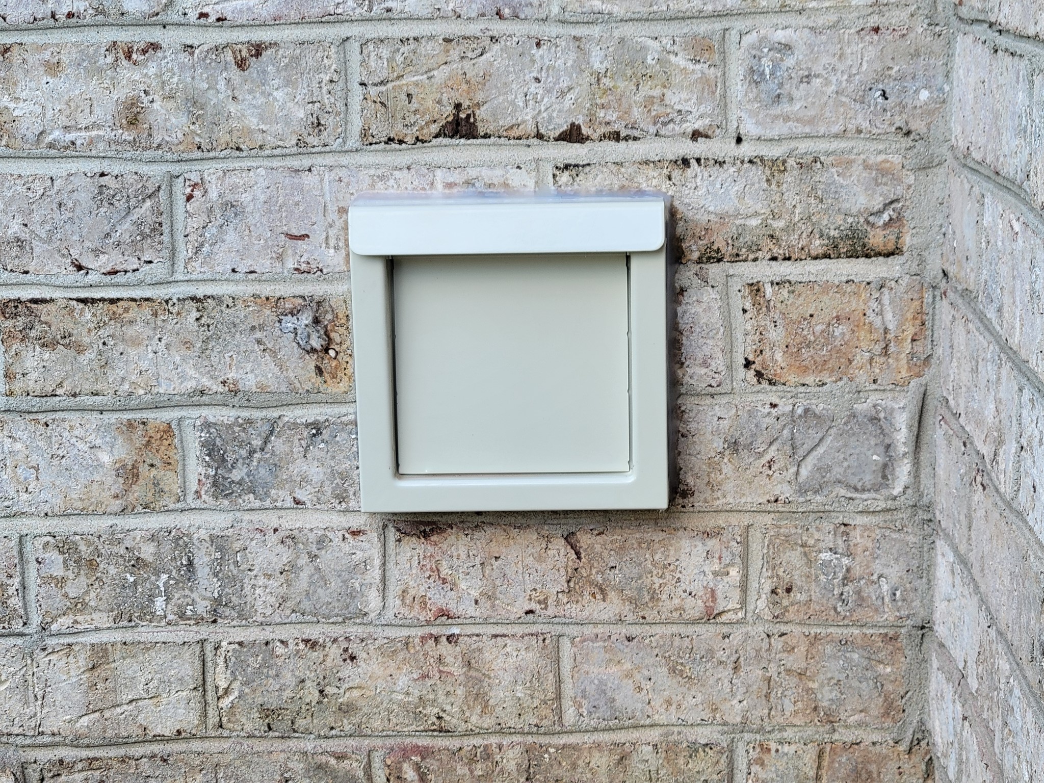
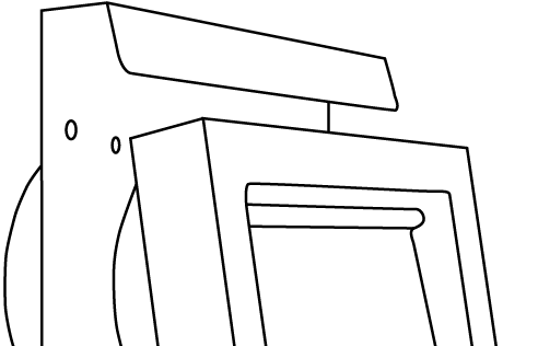
- Heavy Gauge Galvalume® Steel Body
- PPG Envirocron® Powder Coating in White, Tan
or Brown - Lighter Weight Galvalume® Damper (Lighter to
Minimize Restriction) - Intrusion Prevention Balanced Damper Magnets
- Quiet Closing Rubber Damper Bumpers
Model Numbers
 White: DWV4W, Tan: DWV4T,
 Brown: DWV4B, Black: DWV4K
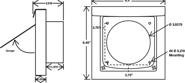
Hole spacing side to side – 4” OC
Hole spacing top to bottom – 3.5” OC
Engineering Files  AutoCAD
  Interchange
Section 11 30 14 - Residential Dryer Venting Specs by Zero Docs: Master Format 04
Installation
Standard Install
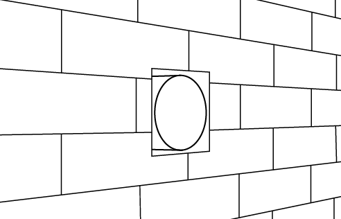
STEP ONE
Confirm that 4” duct is flush to the exterior substrate.
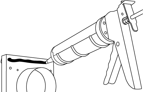
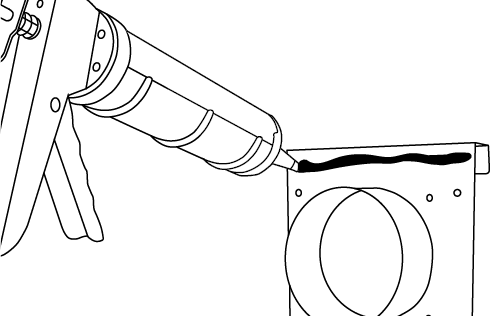
STEP TWO
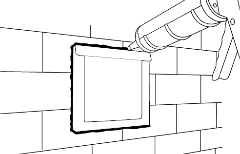
Add sealant around the perimeter of the backing plate.
Add sealant around the perimeter of the backing plate.
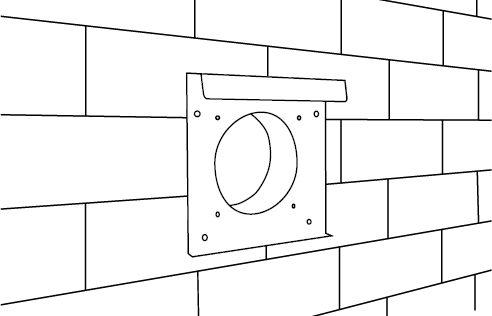
STEP THREE
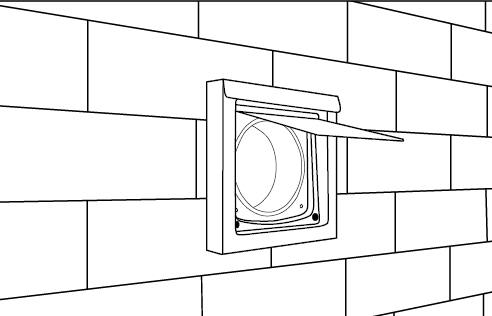
Insert DryerWallVent collar into 4” duct. *If installing a No Collar unit, align opening with duct.
Insert DryerWallVent collar into 4” duct. *If installing a No Collar unit, align opening with duct.
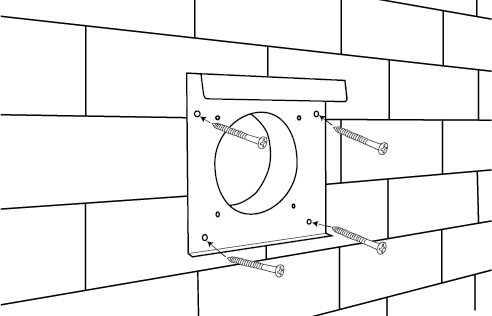
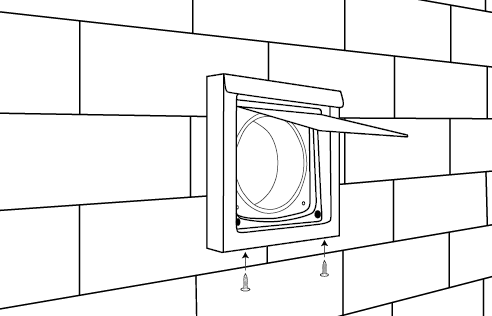
STEP FOUR
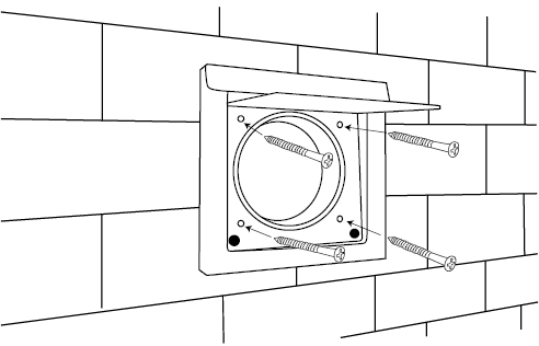
To secure to the substrate, install exterior rated fasteners through the inner screw holes.
To secure to the substrate, install exterior rated fasteners through the inner screw holes.
STEP FIVE
Apply sealant to all sides in contact with final exterior surface.
Tip: Bottom may be unsealed to allow for weeping.
Apply sealant to all sides in contact with final exterior surface.
Tip: Bottom may be unsealed to allow for weeping.
Backing Plate Install
STEP ONE
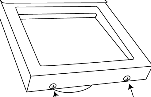
To expose the fastener holes on the backing plate, remove the two #6 screws on the bottom of the DryerWallVent.
STEP TWO
Remove the damper assembly.
Remove the damper assembly.
STEP THREE
Add sealant around the backing plate perimeter.
Add sealant around the backing plate perimeter.
STEP FOUR
Insert DryerWallVent collar into 4” duct. *If installing a No Collar unit, align opening with duct and skip to Step 5.
Insert DryerWallVent collar into 4” duct. *If installing a No Collar unit, align opening with duct and skip to Step 5.
STEP FIVE
Install exterior rated fasteners through the outer backing plate holes.
Install exterior rated fasteners through the outer backing plate holes.
STEP SIX
Insert under the drip edge and secure bottom with the #6 screws.
Insert under the drip edge and secure bottom with the #6 screws.
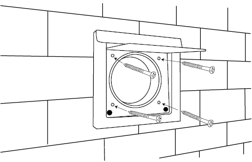
STEP SEVEN
For added security, #14 exterior rated screws may be used in the inner screw holes.
For added security, #14 exterior rated screws may be used in the inner screw holes.

STEP EIGHT
Apply sealant to all sides in contact with final exterior surface.
Tip: Bottom may be unsealed to allow for weeping.
Apply sealant to all sides in contact with final exterior surface.
Tip: Bottom may be unsealed to allow for weeping.